Butane extraction and recycle system

  • Thread starter Graywolf
  • Start date
  • Tagged users None
X

Xtract

4
0
Good idea! My clean sheet of paper system uses 10" Schedule 10 for the pot, to maximize surface area to depth ratio.

My lower plate is machined to accept an O-ring, which the schedule 10 pipe seals against, with clamps holding it in place.

It also has a 4" section of 10" Schedule 10 welded on the bottom of the plate, into which a heating element fits.

The top plate is also machined for an o-ring and is held in place with C-clamps.

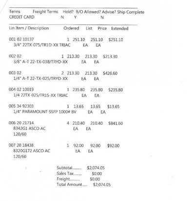
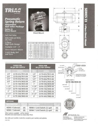
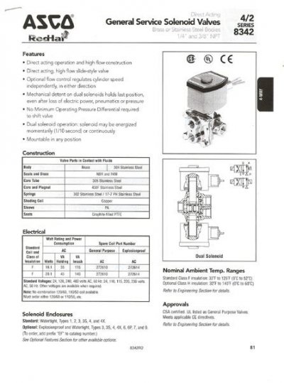
Besides the center port in the top plate, I have five other ports, so that each valve has its own port. That provides room for explosion proof Asco valves, that can be run with a PLC logic controller.[/QUOT
A bit confused by this. So for your new setup you have gotten rid of the paint pressure pot and constructed your own?
Thanks for all your help. Already owning a tamisium and see the benefits to your system, I would also like to manufacture one.
 
Graywolf

Graywolf

1,597
263
Xtract;727943 A bit confused by this. So for your new setup you have gotten rid of the paint pressure pot and constructed your own? [/QUOTE said:
I continue to use the paint pot in my test sled, as it works well, but when designing units from a clean sheet of paper, it is cheaper to build the collection pot than purchase a stainless pot. Otherwise, I would continue to use a paint pot.
 
X

Xtract

4
0
Are you "chunder of love" sebastian from youtube? If not, please ignore.

Nope not me...with the proper fiitings could I use the recovery pump with the tamisium while I waiting on parts.
 
Graywolf

Graywolf

1,597
263
Why not just weld the lower plate to the bottom, instead of paying for a groove to be machined?

I lied!

Got my old laptop cooking again, so I have Auto Cad 2002 LT functioning once more. In detailing the parts for the lower container, I looks like welding is the better solution, especially given that we are heating the bottom, which is hard on O-rings and using an O-ring requires that we use a thicker bottom plate, which weighs about 16 pounds more.

I will post my new design when it is finished.
 
H

hmusic

41
6
I lied!
It looks like welding is the better solution, especially given that we are heating the bottom, which is hard on O-rings and using an O-ring requires that we use a thicker bottom plate, which weighs about 16 pounds more.

I will post my new design when it is finished.

I was also reading about heat and viton o-rings. It appears that they 're temp range is -15ºF to 400ºF. I know you're heating it up a bit, but 400ºF seems a little much. What would the temperature of the bottom plate be, at it's warmest?

Jeez, I wish I hadn't bought that extra flange set now. Another $150 in the hole for nothing. Whatever, I can save it for the next build, or continue with the o-ring plan on the bottom because I really don't think it will be even remotely near 400ºF, or even half that.

P.S. Flare to NPT anyone?
 
Graywolf

Graywolf

1,597
263
I was also reading about heat and viton o-rings. It appears that they 're temp range is -15ºF to 400ºF. I know you're heating it up a bit, but 400ºF seems a little much. What would the temperature of the bottom plate be, at it's warmest?

Jeez, I wish I hadn't bought that extra flange set now. Another $150 in the hole for nothing. Whatever, I can save it for the next build, or continue with the o-ring plan on the bottom because I really don't think it will be even remotely near 400ºF, or even half that.

P.S. Flare to NPT anyone?

As a really old engineer, my thoughts about heat and o-rings are more about time at temperature, than immediate vulnerability. As an old designer, I try to design for zero maintenence, cause shit inevitably seems to happen and old things dry out, crumble, and fall apart.

Sorry about the extra flange, but trust me that you will be surrounded by more new close friends and demand than capacity, once you have an operating system, and you will want more than one.

NPT to flare, describes all of the various sized hose fittings that I use. I buy them at the local refrigeration supply store, to get those also threaded for Schrader valves.

You go bro! Pleased to see you pursuing your dreams! Hee, hee, hee..........................
 
H

hmusic

41
6
NPT to flare, describes all of the various sized hose fittings that I use. I buy them at the local refrigeration supply store, to get those also threaded for Schrader valves.
Everything made sense until you mentioned "Schrader valves". Where do you use them, and why?

Also, how do you purge off non-compressible gasses using the in-line valve on the vapor return line (going to refrigerant cylinder)? Do you disconnect it from the recovery machine first? Sorry if this seems like a stupid question to you.
 
Graywolf

Graywolf

1,597
263
Everything made sense until you mentioned "Schrader valves". Where do you use them, and why?

Also, how do you purge off non-compressible gasses using the in-line valve on the vapor return line (going to refrigerant cylinder)? Do you disconnect it from the recovery machine first? Sorry if this seems like a stupid question to you.

Schrader valves are the same valve used in tires. They are typically in refrigeration flare fittings, but in this case, I took them all out, so it is moot.

My hose between the recovery machine and the tank has a valve in-line. I close it to isolate the recovery machine and loosen the vapor line fitting at the tank.
 
H

hmusic

41
6
Here's a preview of my new "dream"...

Will be doing some pressure/vac testing tomorrow, then, some "real world" testing...

Then, I'm gonna start my own thread, and give all praise and glory to GRAYWOLF!
 
Extractor 3000 almost there
T

treehugger

154
18
thinking in terms of "mode of failure" the extracting column looks somewhat precarious perched up on top of that valve, would a bump or shock tend to snap the top off of the rig?
 
Graywolf

Graywolf

1,597
263
Here's a preview of my new "dream"...

Will be doing some pressure/vac testing tomorrow, then, some "real world" testing...

Then, I'm gonna start my own thread, and give all praise and glory to GRAYWOLF!

The praise and glory go to you for designing and building your own, just like I did after seeing FOAF's preliminary work bro!

Have fun shaking it out!
 
mountain

mountain

71
8
I lied!

Got my old laptop cooking again, so I have Auto Cad 2002 LT functioning once more. In detailing the parts for the lower container, I looks like welding is the better solution, especially given that we are heating the bottom, which is hard on O-rings and using an O-ring requires that we use a thicker bottom plate, which weighs about 16 pounds more.

I will post my new design when it is finished.

would you be willing to share the new cad design that you mentioned in your post?

anything you can share would be REALLY appreciated!!!

pm if you prefer...
 
Graywolf

Graywolf

1,597
263
would you be willing to share the new cad design that you mentioned in your post?

anything you can share would be REALLY appreciated!!!

pm if you prefer...

Be happy to when it is finalized. Quotes on the first design proved to be too expensive to have built by a local CNC waterjet cutting and maching shop, so I am scheming cheaper alternatives.
 
Graywolf

Graywolf

1,597
263
Updates on progress:​
Well, progress is going slower than planned, with illness rearing its ugly head amongst usn's cadre of graying, hoary moss covered retired machinists.

Here is the only two pieces in the basic system, that require machining or welding, and you can see how easy they are to make. They still need to be cleaned and polished, but the attached pictures show what they look like immediately after fabrication.

The center plug in the pressure pot lid was bored for an easy slip fit on a 3/4" 1.050" OD Schedule 40 316SS pipe, with 10.5" sticking out the bottom of the plug and 3.5" sticking out the top. This is where the valves and column attach.

The paint port lid was also modified by cutting off the wrench boss and boring for the same 3/4" pipe. This will be for the control valves and pressure switches.

We decided on pneumatic operators on full port stainless ball valves. All are air to open or close, except the butane supply valve, which is a normally closed, spring return valve for safety.

The three and four way Asco solenoid valves for the air, will allow us to separate the electrical functions from the extraction area, for explosion proof protection.

More pictures and details of the valves that I've ordered and the prices at the link below. Keep in mind that manual valves can be used at significantly less cost.

http://skunkpharmresearch.com/projects/
 
Terpenator machined parts 1 1
Terpenator machined parts in place 1 1
Terpenator MK II valve list 1 1
Turpenator MK II Valves 2
Turpenator MK II Valves 3
Turpenator MK II Valves 4
Top Bottom