Log In Register

justanother stealth, DIY, 2x 150 HPS bud box, ...bozo style!

  • Thread starter Thread starter justanotherbozo
  • Start date Start date
  • Tagged users Tagged users None

justanother stealth, DIY, 2x 150 HPS bud box, ...bozo style!

justanotherbozo 43 Replies 16,554 Views
Page 1 of 3 · Replies 1–20 of 44
justanotherbozo

justanotherbozo

Posts
952
Reactions
1,571
Joined
Jul 3, 2009
Points
143
well, finally, i've got my new fruiting chamber close enough to finished that i can
start paying attention to my other responsibilities, lol.

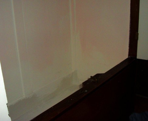
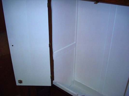
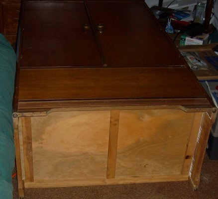
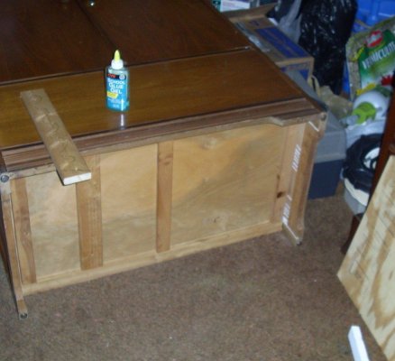
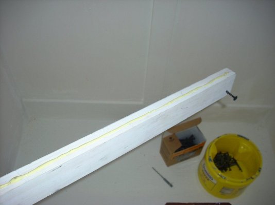
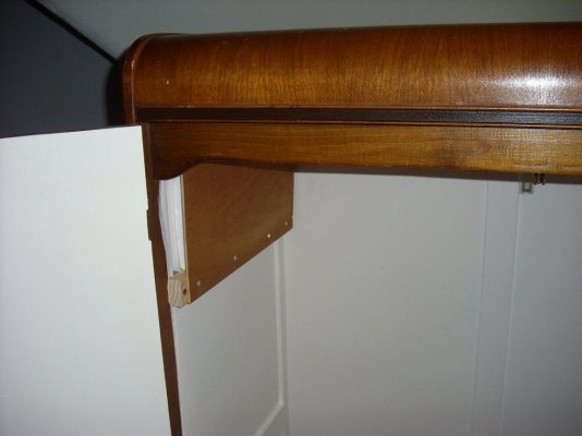
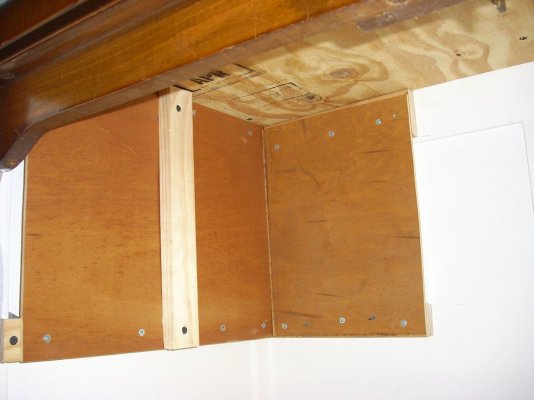
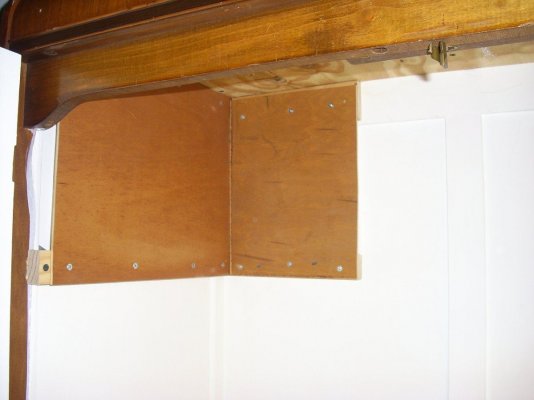
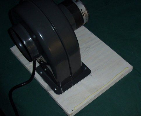
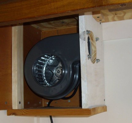
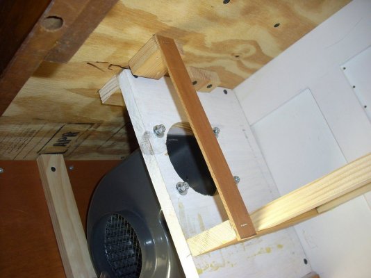
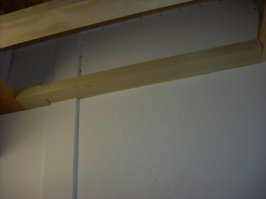
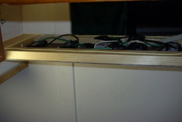
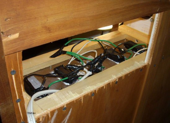
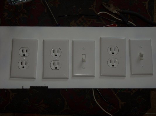
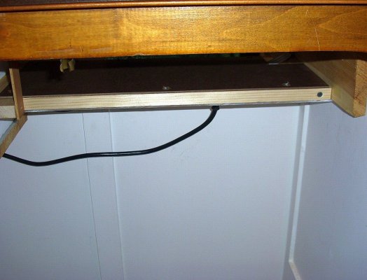
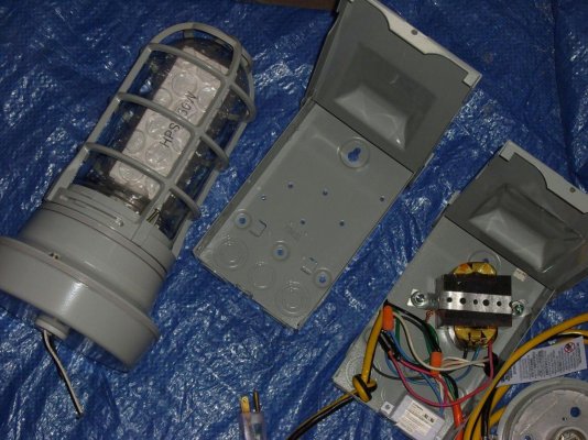
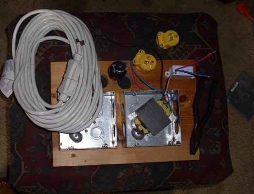
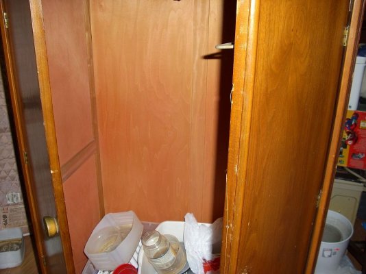
anyway, this thread is to document what i went through to convert this old
'closet' i found in a Salvation Army store, 61'Hx33'Wx18D, into a micro bud
box. ...lol, and it's been a real pain in the posterior!

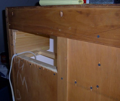
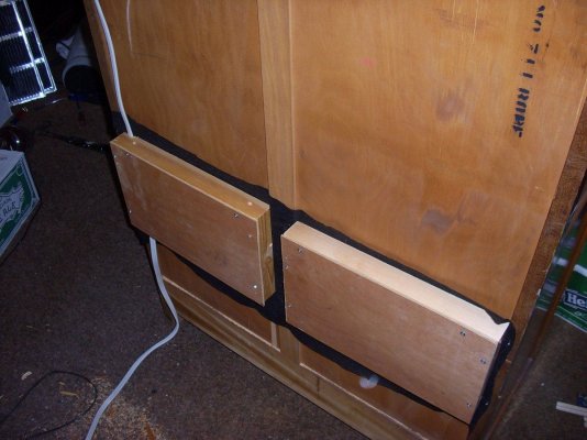
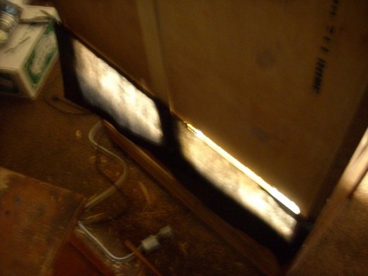
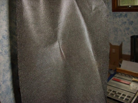
here's a few pics to get things started.

note the addition of the lock in the last 2 pics.
 

Attachments

  • justanother-stealth-diy-2x-150-hps-bud-box-bozo-style-2.jpg
    justanother-stealth-diy-2x-150-hps-bud-box-bozo-style-2.jpg
    96.7 KB · Views: 1,000
  • justanother-stealth-diy-2x-150-hps-bud-box-bozo-style.jpg
    justanother-stealth-diy-2x-150-hps-bud-box-bozo-style.jpg
    121.9 KB · Views: 1,059
  • justanother-stealth-diy-2x-150-hps-bud-box-bozo-style-5.jpg
    justanother-stealth-diy-2x-150-hps-bud-box-bozo-style-5.jpg
    135.9 KB · Views: 949
  • justanother-stealth-diy-2x-150-hps-bud-box-bozo-style-3.jpg
    justanother-stealth-diy-2x-150-hps-bud-box-bozo-style-3.jpg
    76.3 KB · Views: 979
  • justanother-stealth-diy-2x-150-hps-bud-box-bozo-style-4.jpg
    justanother-stealth-diy-2x-150-hps-bud-box-bozo-style-4.jpg
    132.1 KB · Views: 956
then, here, you can see i painted the interior and i used a mix of elastomeric
paint and some flat white ceiling paint i had laying around. ...i like the elastomeric
paint because it's cheap at about $16.00 USD per gallon, it's highly reflective
and it's rubberized so waterproof and mildew resistent.

note also that i added some fabric to the bottom for added strength. ...what i did
was to lay a coat of paint on the floor and, while it was still wet, i laid a piece of
landscaping fabric into the wet paint, then, once dry, i put a few coats more, lol.

also, i added a lip across the bottom of the doorway, partly to make light
proofing easier and partly to give myself something to latch the left hand
door to.
 

Attachments

  • 007.jpg
    007.jpg
    119.6 KB · Views: 837
  • 008.jpg
    008.jpg
    104.4 KB · Views: 818
  • 009.jpg
    009.jpg
    83.9 KB · Views: 776
  • 010.jpg
    010.jpg
    129.9 KB · Views: 779
  • 011.jpg
    011.jpg
    132.7 KB · Views: 765
  • 006.jpg
    006.jpg
    156.3 KB · Views: 894
...here i see it's a good thing i decided to reinforce the bottom! lol.
 

Attachments

  • 012.jpg
    012.jpg
    107.5 KB · Views: 689
  • 013.jpg
    013.jpg
    117.5 KB · Views: 670
  • 014.jpg
    014.jpg
    118.2 KB · Views: 665
  • 015.jpg
    015.jpg
    123.2 KB · Views: 650
here's a few shots of that lip i installed with my solution for locking the
left side door. ...it may not be easy to see but i drilled a hole in that lip big
enough for a plastic bushing which, in this application, now became a collar
for the latch to slide into when in the locked position, my intent was to make
it more durable.
 

Attachments

  • 016.jpg
    016.jpg
    75.6 KB · Views: 620
  • 018a.jpg
    018a.jpg
    132.5 KB · Views: 583
  • 018.jpg
    018.jpg
    83.4 KB · Views: 589
  • 017.jpg
    017.jpg
    46.1 KB · Views: 613
btw, this thing was a real steal at like $65.00 i think! ...when i saw it i knew
it was perfect!

anyway, here's a few more shots with a few missing as i see i don't have pics
of the latter part of this stage, ...note in the first pic here the pieces of wood
screwed to the ceiling, what i did was to fill the space between those pieces
of wood with foam and then i added a piece of 1/2 inch plywood, i wanted to make
sure i had a very solid ceiling to attach things to.
 

Attachments

  • 019.jpg
    019.jpg
    76.6 KB · Views: 564
  • 020.jpg
    020.jpg
    135.6 KB · Views: 557
  • 021.jpg
    021.jpg
    92.4 KB · Views: 547
  • 022.jpg
    022.jpg
    81.7 KB · Views: 521
...here you can see the fan\filter combo i'm using, a 180CFM squirrel cage
blower and a Can2600 carbon scrubber.

...in the last pic here you can see that plywood ceiling i spoke of as i install
the first piece of the box i built to house the fan.

i got the idea to use the foamboard and box the fan like this from a friend over
at Green Passion, another site i participate in which is more geared to helping
med users learn to grow. ...anyway, my friends name is tokecrazy and you can
see his muffler box here.

can you dig my 'flange', lol?
 

Attachments

  • 026.jpg
    026.jpg
    80.6 KB · Views: 540
  • 024.jpg
    024.jpg
    113.3 KB · Views: 558
  • 023.jpg
    023.jpg
    103.4 KB · Views: 588
  • 025.jpg
    025.jpg
    62.2 KB · Views: 543
...and a few more, lol.
 

Attachments

  • 036.jpg
    036.jpg
    79.8 KB · Views: 478
  • 035.jpg
    035.jpg
    110.6 KB · Views: 474
  • 034.jpg
    034.jpg
    102.1 KB · Views: 457
  • 033.jpg
    033.jpg
    87.1 KB · Views: 467
  • 032.jpg
    032.jpg
    129 KB · Views: 470
...here, as the fan goes in, you can see how much i was inspired by
tokecrazy's DIY fan box with the only fundamental difference being
that mine is hard-mounted in the cab rather than being suspended
within the cab.
 

Attachments

  • 037.jpg
    037.jpg
    108.5 KB · Views: 701
  • 038.jpg
    038.jpg
    126.2 KB · Views: 680
  • 039.jpg
    039.jpg
    89.6 KB · Views: 664
  • 040.jpg
    040.jpg
    96.6 KB · Views: 645
  • 041.jpg
    041.jpg
    130.9 KB · Views: 660
  • 042.jpg
    042.jpg
    122.4 KB · Views: 639
  • 044.jpg
    044.jpg
    111.5 KB · Views: 630
Nice!!!! :party0042:

thanks man.

...anyway, here, as i begin to build the box for the exhaust, you can see one of the
many wrinkles i had to deal with.

note that in pic #3, the wood is split and in pic #4 you can see the result as
i throw in a couple screws from the back.

lol, pic #5 shows the replacement.
 

Attachments

  • 049.jpg
    049.jpg
    100.1 KB · Views: 556
  • 048.jpg
    048.jpg
    121.4 KB · Views: 560
  • 046.jpg
    046.jpg
    139.4 KB · Views: 586
  • 047.jpg
    047.jpg
    167.8 KB · Views: 575
  • 045.jpg
    045.jpg
    56.9 KB · Views: 585
...in pic #2 you can see my solution to another small wrinkle, i should have
installed that small piece of wood before i put the frame below it, now i can't
fit the drill, ...lol, oh well, that's what glue is for!
 

Attachments

  • 050.jpg
    050.jpg
    63.1 KB · Views: 523
  • 051.jpg
    051.jpg
    136.6 KB · Views: 522
  • 052.jpg
    052.jpg
    79.9 KB · Views: 507
  • 053.jpg
    053.jpg
    118.3 KB · Views: 503
  • 054.jpg
    054.jpg
    71.9 KB · Views: 495
  • 055.jpg
    055.jpg
    54.4 KB · Views: 494
...now here you can see my solution to electricals.

keep in mind that, if you are unfamiliar with electrical stuff, you should at
least have someone else look at your work before you fire it up, or you
might really be firing it up!

electricity is no joke, if you make a mistake here, it could cost you
everything, including your life and family, as well as your home.
so be very sure you have everything right. ...this is a part of the
job where the concept of 'measure twice, cut once' really applies.
 

Attachments

  • 056c.jpg
    056c.jpg
    86.5 KB · Views: 494
  • 056e.jpg
    056e.jpg
    66.6 KB · Views: 477
  • 056d.jpg
    056d.jpg
    144.7 KB · Views: 478
  • 056b.jpg
    056b.jpg
    72.1 KB · Views: 506
  • 056a.jpg
    056a.jpg
    166.5 KB · Views: 518
  • 056.jpg
    056.jpg
    164 KB · Views: 525
as you can see from the pictures in the last posting, no measuring required, lol!

anyway, note that there are 2 switch's, the one on the far right is a kill switch
for the entire cab, the other switch is to control the outlets that will house the
lights, in case i need to shut them off while i work in there, it gets VERY bright
in there, lol.

...now, here's a couple before and after's.
 

Attachments

  • 057.jpg
    057.jpg
    85.7 KB · Views: 451
  • 058.jpg
    058.jpg
    130.8 KB · Views: 432
  • 059.jpg
    059.jpg
    146.4 KB · Views: 440
  • 060.jpg
    060.jpg
    137.1 KB · Views: 420
...here you can see the beginnings of my intakes, something i'm in the process of
altering and enlarging, i need to make it more open than it is, so look for an update
next week, lol.

note the the first hole i drilled splintered in back, if you are gonna
work with veneer, be sure you either tape up the back, or score
it, otherwise it will splinter and make for a messy job.
 

Attachments

  • 067.jpg
    067.jpg
    69.3 KB · Views: 391
  • 066.jpg
    066.jpg
    56.9 KB · Views: 389
  • 065.jpg
    065.jpg
    118.9 KB · Views: 384
  • 063.jpg
    063.jpg
    134.9 KB · Views: 401
  • 062.jpg
    062.jpg
    47.3 KB · Views: 408
  • 061.jpg
    061.jpg
    54.8 KB · Views: 412
  • 064.jpg
    064.jpg
    50.3 KB · Views: 411
  • 068.jpg
    068.jpg
    56.1 KB · Views: 388
  • 069.jpg
    069.jpg
    64.8 KB · Views: 379
here are the rest of the intakes and, like i already said, this isn't working, with the intakes
as they were built, my temps were in the high 80's, sometimes in the low 90's and, while
they will grow, i want to get my temps down to the high 70's at least, lol.

so, lol, if you are reading this, don't do your intakes like this as you won't be happy!

oh yeah, btw, that black fabric is just landscapers fabric, made to prevent weeds, lol.
 

Attachments

  • 079.jpg
    079.jpg
    92.4 KB · Views: 362
  • 077.jpg
    077.jpg
    66.5 KB · Views: 366
  • 076b.jpg
    076b.jpg
    142.6 KB · Views: 369
  • 076a.jpg
    076a.jpg
    141.6 KB · Views: 381
  • 075.jpg
    075.jpg
    99.2 KB · Views: 376
  • 073.jpg
    073.jpg
    237.5 KB · Views: 398
  • 070a.jpg
    070a.jpg
    66.5 KB · Views: 385
...now i start the wiring for the lights, so i can remote the ballasts.

pic #1 shows where the ballasts will be housed and the others show the
box's i'll be putting the ballasts into and the sockets and plugs i'm using
for the lights. ...i wanted them to be removable so i could replace bulbs
without hassle.

and the last three shots, first, the light as it came out of the box and the box
i planned to put the ballast into, ...to the right you can see the first light already
done.

second, the light disassembled, and third, a wiring diagram that helped a lot.
 

Attachments

  • 080.jpg
    080.jpg
    119.5 KB · Views: 400
  • 081.jpg
    081.jpg
    154.2 KB · Views: 389
  • 082.jpg
    082.jpg
    131.6 KB · Views: 377
  • 082a.jpg
    082a.jpg
    118.2 KB · Views: 374
  • DSCI1296smll.jpg
    DSCI1296smll.jpg
    184 KB · Views: 379
  • DSCI1300smll.jpg
    DSCI1300smll.jpg
    189.2 KB · Views: 375
  • 10099pic03.jpg
    10099pic03.jpg
    28 KB · Views: 391
here you can see as i wire up the ballasts.

i know this is frowned on and i hope nobody minds too much, it's just that i really
believe in giving credit where it is due and it was this thread that taught me how
to do this and, as important as electrical safety is, i thought it'd be ok.

if you want more details on how this is done, here is a link to a thread
by Quazi, a DIY wizard over at ICMag and he's classy enough so he posts
the thread that taught him how to do it and i'd recommend you read that
thread as well, you can't have too much info when it comes to electrical's.

How To Remote Ballast a 150W HPS Vapor Tight Light
 

Attachments

  • 083.jpg
    083.jpg
    158.8 KB · Views: 394
  • 084.jpg
    084.jpg
    165.8 KB · Views: 381
  • 085.jpg
    085.jpg
    165.4 KB · Views: 368
  • 086.jpg
    086.jpg
    181.1 KB · Views: 378
  • 087.jpg
    087.jpg
    176.3 KB · Views: 365
Page 1 of 3 · Replies 1–20 of 44
Back
Top Bottom